Now that my "learning" curve has eased out I finally got time to carry on in my personal projects / hacks. And this time I promise I will put some proper code and tutorials (by the way I have enabled the comments so feel free to comment code in the older entries).
So this first new entry is related to the fact that I just received an Oculus Rift. This HMD is called to push the VR back in the trenches and I wanted to try it first hand... It promises real-time head tracking and perfect 3D vision of the environment with an epic field-of-view. You can move around the scenarios and after 3 minutes you truly believe you are inside. But head tracking is not everything in Virtual Reality and there is still some edges to cut: one of those is solving the problem of "moving around" with some kind of localization and I will talk about that one at some point; but the interesting one today is interacting with the environment, and when I say interacting I mean shooting at things... time for some Virtual Reality FPS.
I want to create a Gun that I could use in a shooter game, kind of the one Nathan has created for Half-Life 2 here. But that gun has some drawbacks (economic drawbacks because he is buyin a custom weapon and a custom tracker) and I want something cheap and nice and custom and hacky and ... and ... and I want it now. So this and the next posts will talk about creating your very own Gun Controller with tracking and everything for playing in virtual worlds!
Chapter 1: Ripping apart a Nerf Gun and giving it an Arduino brain.
Lets start from the beginning. In this first chapter I will talk about how I opened a plastic gun and closed a electronic one. I will cover how I made the connections from plastic to Arduino inputs and by the end the result will be a gun being able to fire, reload and select alternative fire. Lights/vibration and tracking will come in the next chapters.
Materials:
The gun: I used a Nerf Gun, the model "Alpha Trooper" have a lot of space inside to maneuver and also looks bad-ass. Actually I bought it to shot foam darts at people at the office... and yes we painted them and everything.
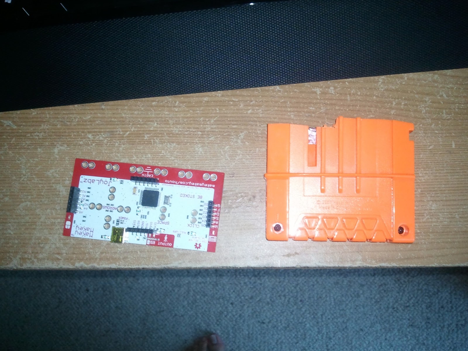
The brain: I have got a Makey Makey, which is basically an Arduino Leonardo. I bought it just to have fun until this project came to my mind! This is not supposed to be a Makey Makey / Arduino tutorial so go to the official forums in case of doubt.
The guts: Some cables, some springs, a solder, a saw, screwdriver and aluminium tape!
Step 1: Unscrew everything
With a star-screwdriver and patience I just simply removed al the screws. Once done, very carefully I removed and keep al the moving-pieces of the gun as you can see in the photo.
 |
| Dismounted Alpha Trooper |
I enumerated the pieces and I will use this photo as reference over and over again. Always keeping all the springs I disposed the pieces 13,14 and 15.
The other big problem is the piece 1. This piece
moves using the side rail and when in "firing" mode takes all the space in the center in order to load the bullet. When cutting it it is important to note that I still needed the 2 hangers for the rails on each side of the gun. And I still wanted to be able to move the piece 4 for realism. So the outcome is cutting to something like this.
Fine! Now I should be able to put the Makey Makey inside, but I still want to be able to remove it sometimes and It must float inside the gun so it does not interfere with the piece 1 moving rails.
I decided to cut a small slot with a saw where the end of the clip should rest. The next photo will highlight this.
Step 2: Making space for the board
As you may see in the top-right corner of the previous photo, the Makey Makey is not very big but I still have to make some room. The picked place is exactly the center, on top if the magazine, but that position will give a couple of problems.
 |
| "resized" clip |
When the ammunition clip is in, it takes almost all the space... so I will cut it with a saw! Always saving the gap in the side that keeps it hooked to the gun.
This picture compares the resize clip to the board. I also removed all the inner parts such as the springs and the platform that you may see in the previous photo.
 |
| "resized" piece1 |
moves using the side rail and when in "firing" mode takes all the space in the center in order to load the bullet. When cutting it it is important to note that I still needed the 2 hangers for the rails on each side of the gun. And I still wanted to be able to move the piece 4 for realism. So the outcome is cutting to something like this.
 |
| A 1cm cut to serve as slot for the board... |
I decided to cut a small slot with a saw where the end of the clip should rest. The next photo will highlight this.
 |
| Cutting in half the piece 11 |
Last, the piece 11 which serves as chamber for the foam bullet is also in the way. Show no mercy removing the right side of it. Always keeping in the "right" side the two small legs to attach it to the body.
And now it the gap is big enough the Makey Makey should fit inside and don't move at all, it is important to note that the piece 1 must be in first, and be sure that its movement is not blocked by the board.
 |
| The Arduino board inside the Gun with all pieces |
Step 3: Making the triggers talk
The real fun starts now. With some aluminium tape and cables the trigger (piece 3), pump system(piece 2) and the magazine should inform to the Makey Makey of their state.
To do so I followed this principle: moving part should now have any cables but being used to close circuits "printed" in the fixed pieces. How does this apply? Easier than it sounds, simply put aluminium tape in the moving parts that, when in on position will touch other 2 aluminium pieces connected to the board. Let's see some close ups.
 |
| Pump system circuit |
This is the edge of the piece 2. Some aluminium tape in the orange part that moves as the very-nice-orange-arrow indicates will connect the red and green areas. It is important to note that the tape must be flat enough to avoid giving too much friction to the moving part. Note how instead of putting directly the cable I allow a big and separated area in the "tape circuit". This cables should go to ground and a input pin in the board later.
 |
| Trigger system circuit |
 |
| Reload system circuit |
Two hard metal springs glued strategically in the gun side, so they block partially the clip entrance, but still holds will do it. Always putting some aluminium tape in the clip so it connects both springs which have cables going to the board as always.
 |
| Flap to remove in the left side |
The final bits include guiding the cables from the tape areas to the board. The Alpha Trooper has enough room behind the trigger to do so. But on the other side of the gun a little flap must be removed.
Removing it will allow some space to guide all the cables through when closing it.
And the very final thing is the USB cable, this step is a bit special, eventually this mod will be wireless with the help of an android phone, but for now an USB connection to the PC is needed. The default cable that comes with the board is a normal mini-usb that won't fit properly between the board connector and the piece 6 so it is important to get a mini-usb with the mini-head output rotated 90 degrees. This is not easy to find in stores as they come customised directly with some cameras. Lucky me a friend gave me one.
 |
| Path for the USB cable |
In the photo I left in red the places where I made a hole, blue for the x-ray vision on the cable and green for highlighting where I removed the flap (in the other side). Please note that here I am not using the 90 degrees cable but the normal one.
Step 4: Test and close
It is time to seal this mess and give it a try. For doing all that is needed is to simply connect the USB cable to the PC and check if and only if one of the circuits is closed the LED in the board goes green. Pro tip: change the current springs in the gun with those removed from previous pieces in order to have stronger springs in the modified parts.
Now turn to put all the items in and put back the screws.
 |
| It is alive! |
 |
| Final look opened |
 |
| Final Look Closed |
Next Step: Programming and LEDs
My next step in the agenda is to do some custom programming to the current Makey Makey script in order to fire the keys for the clip and pump just once when the clip is removed or the or the lever pressed. And also add some AND gates to the trigger so it only shots if there is a clip in possition.
I would also love to add some funny LEDs arrays behind the piece 7 and animate them when doing actions so stay tuned.
After that another post should come with some info about how to make this all wireless and do some tracking using the gyroscope of an Android phone.
No comments:
Post a Comment